The Pitch
1. The pitch surface
Football can be played on almost any surface, but if the ball bounces in the wrong direction, because the player has limited skills, it is easy to blame the pitch. To prevent players hiding behind this popular excuse, it is necessary to provide a pitch with a flat and even surface in different seasonal weather conditions.
1.1 Artificial turf
Due to the situation, described above, the British inventor Ralph Leather Rylance designed an entirely artificial pitch surface as early as in 1881 (GB 1881-7A). It did no longer have anything in common with your average natural grass field. His invention consisted of a concrete, asphalt or wooden plank foundation with a rubber layer applied on top. Depending on the use and the sports grounds the rubber utilised was to be either solid, spongy or moulded.
Modern surfaces aim at simulating a natural grass pitch. It is true that in 1930 rubber was still used for this purpose but it was a fibrous material to simulate grass blades (US 1 939 846 A). In 1965, the Monsanto company applied for a patent in Germany for its multi-layer artificial turf (DE-OS 15 78 824). A weather-resistant synthetic woven backing on an elastomer served as a basis for pile filaments of synthetic ribbons. Latex was used to bond the individual layers together.
![]() Figure 1: Multi-layer artificial turf (US 3 661 687 A)
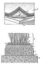
Figure 1: Multi-layer artificial turf (US 3 661 687 A)
However, artificial turf alone is not sufficient for providing a playable pitch. The turf of the top surface must be combined with several layers underneath which provide an additional shock-absorbing quality. They must also have high mechanical strength and durability for the rigours of regular football matches and be permeable to water, as shown in the US patent 3661 687 A (see Figure 1).
Recently, inventions have focused on duplicating the characteristics of natural soil and grass to the greatest extent possible to enable game situations that are like those on natural grass. This is also the aim of DE 198 22 542 C1 which describes an artificial turf consisting of U-shaped tubes which will absorb water and simulate the slipperiness of wet grass. EP 0 966 568 B1 and DE 10 2004 013 749 A1 present two further examples of modern types of artificial turf. The first focuses on an increased flexibility of the multilayered material and the second invention describes a synthetic moisture-controlling pitch surface made of multi-filament yarn.
Those who are familiar with astroturf pitches know that an infill material (either sand or crumb rubber) is evenly spread between the artificial grass blades to make the pitch playable.
![]() Figure 2: Maintenance machine for artificial turf (DE 20 2007 015 031 U1)
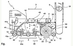
Figure 2: Maintenance machine for artificial turf (DE 20 2007 015 031 U1)
The infill material adds weight to help keep the surface flat and level, preventing the astroturf from folding up like a carpet in certain situations during the match. However, from time to time, when the fibres need to be cleaned and fluffed, the infill material has to be removed by a vacuuming, brushing or combing device. Figure 2 (DE 20 2007 015 031 U1) shows a machine that was specifically developed for this purpose. This special sweeping machine has a rotating cylinder (41) with 40 teeth that works at a right angle to the direction of motion (3) to remove the infill material from the base of the pile.
When the plastic material is worn out the astroturf has to be completely replaced ? this may be necessary every four to twelve years. Special machines are required for this purpose: on the one hand, to cause the least possible damage and, on the other hand, to ensure recycling of individual components of the turf material (EP 1 319 753 B1).
| Publication number | Year | Title | Brief description |
|---|---|---|---|
| DE 20 2007 015 031 U1 | 2007 | Fahrbare Vorrichtung mit einer Abtragvorrichtung für das Füllgut auf einem Kunstrasenplatz | Sweeping machine to remove infill material spread between astroturf fibres to increase stability |
| DE 10 2004 013 749 A1 | 2004 | Kunstrasen | Moisture-controlling artificial turf for football pitches |
| EP 1 319 753 B1 | 2002 | A process for removing synthetic-grass floorings, corresponding use and product | Removing of synthetic-grass floorings with simultaneous recycling of individual components of the turf material |
| EP 0 966 568 B1 | 1998 | Synthetic turf | Multilayer artificial turf with increased flexibility for sports purposes |
| DE 198 22 542 C1 | 1998 | Kunstrasen mit hohlen Halmen | Artificial turf consisting of U-shaped tubes with water absorption properties which help to simulate the play on wet grass |
| US 3 661 687 A | 1972 | Artificial grass sorts field | Combination of artificial turf and sub-layers to provide an optimum field for sports and ball games |
| DE-OS 15 78 824 | 1966 | Künstlicher Rasen | Woven artificial turf |
| US 1 939 846 A | 1930 | Artificial turf and method of making the same | Artificial turf of fibrous rubber |
| GB 1881-7 A | 1881 | Artificial Floors for Football, Bowling, Lawn Tennis, &c. | Artificial floors for ball games, eg. football, whose pitch surface consists of suitable rubber layer |
Hybrid turf and its production
Today, hybrid turf has become an indispensable feature of numerous football stadiums around the world. It is designed to combine the robust properties of artificial turf with the good playability of natural grass. For hybrid turf, as for artificial turf, the requirement is to create a durable surface with properties similar to those of a natural turf.
Here are a few examples of the wide variety of hybrid turf surfaces:
The hybrid turf can be built up in layers as in US 2018 / 0 030 670 A1. The focus is on controlling the water balance and achieving good shock absorption properties.
WO 16/ 122 389 A1 (Artificial hybrid turf) shows a solution to improve the durability of a hybrid turf pitch. This is achieved by a net-like reinforcement layer.
The utility model DE 20 2015 104 216 U1 focuses on subsequent disposal (Faserbewehrte Rasentragschicht): Since synthetic fibres do not decompose, the solution proposed here uses synthetic fibres that are made biodegradable with the help of a physical effect - for example by means of a certain temperature, humidity, UV radiation.
There are several novel approaches to producing hybrid turf:
DE 601 11 738 T2 shows a device that inserts the synthetic fibres at regular intervals into a ground surface when moving over it. The device contains a large number of rolls with fibre material. In this process, the synthetic fibres can be inserted either before or after sowing the natural grass or into an existing turf.
A similar machine is described in the utility model DE 202016104972 U1: The guidance of several synthetic fibre strands around a rotating drum with cutting device aims at inserting the synthetic fibres faster and thus more economically.
DE 10 2014 011 714 B3 describes a method of creating hybrid turf or artificial turf: A machine lays synthetic turf mats and, at the same time, fills them with the appropriate filling material, so that the laying can be done in one go only. Since seeds from a natural grass turf can also be added to the filling material, the method is suitable for both artificial and hybrid turf production.
| Publication number | Year | Title | Brief description |
|---|---|---|---|
| US 2018 0 030 67 0A1 | 2018 | Substructure for an artificial lawn | |
| WO 2016/122 389 A1 | 2016 | Artificial hybrid turf | |
| DE 20 2015 104 216 U1 | 2015 | Faserbewehrte Rasentragschicht | |
| DE 601 11 738 T2 | 2000 | Verfahren zum Einbringen von Fasern in eine Oberfläche und Vorrichtung zur Durchführung dieses Verfahrens | |
| DE 20 2016 104 972 U1 | 2016 | Vorrichtung zum Einsetzen künstlicher Grasstränge in den Boden | |
| DE 10 2014 011 714 B3 | 2014 | Verfahren zur Herstellung eines Hybridrasens oder Kunstrasens sowie Maschine zur Durchführung des Verfahrens |
1.2 Under-pitch heating
![]() Figure 3: Under-pitch heating (GB 631 291 A)
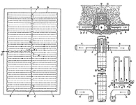
Figure 3: Under-pitch heating (GB 631 291 A)
No other season plays such an important role in football than winter. It is difficult to play on an icy or even snow-covered pitch. As early as 1947, Edwin Knott circumvented these problems by inventing the probably first under-pitch heating (GB 631291 A, see Figure 3). Hot steam was fed to a pipe system that ran under the whole pitch for preventing freezing of the ground. A few years later, a similar system was depicted in the patent DE 924 931, suggesting that the same pipe system should serve to drain the pitch in rainy weather and to heat it in snowy weather.
In DE-OS 20 18 859 a more radical approach is described: A cellar is built underneath the whole of the pitch. During heavy rainfall a drainage system will drain off the water and feed it into water tanks in the cellar. However, these drainage pipes are not used for heating as well. In the winter, the whole of the cellar will be heated and the waste heat will keep the pitch free of ice.
During recent years, research has made very considerable contributions to the development of particularly wear-tolerant and durable grass seed mixtures for pitch surfaces that can remarkably well withstand the adverse effects caused by heating. Nevertheless, the problem still remains of how to create or maintain acceptable temperatures for football turf. EP 1 442 654 B1, for example, deals with solutions of these problems.
The main objective of recent further developments is to achieve optimised heat regulation within the ground combined with the most efficient heating system possible.
Two examples:
US 6 689 447 B2 shows several options for arranging electric heating cables or water pipes. DE 102012016909 B3 describes a layered structure of the ground in which heated air flows through a layer in order to quickly heat up the surface.
| Publikationsnummer | Jahr | Titel | Kurzbeschreibung |
|---|---|---|---|
| EP 1 442 654 B1 | 2003 | Vegetation ground temperature control method | Verfahren zur Steuerung der Temperatur eines bepflanzten Untergrundes |
| DE-OS 20 18 859 | 1970 | Wetterunabhängiges Fußballfeld | Unterkellerung eines Spielfeldes zur Kompensation von Wettereignissen, die den Spielbetrieb gefährden: Bei Regen, Regenauffangbecken via Drainagen, im Winter Heizung des Spielfeldes durch Heizen des Kellers |
| DE-PS 924 931 | 1951 | Einrichtung zur Enteisung, Be- und Entwässerung von Sportfeldanlagen und Nutzbodenflächen | Drainage und Heizung von Rasenflächen mittels eines im Spielfeldboden verlegten Röhrensystems |
| GB 631 291 A | 1947 | Improvements in Means for Drying and/or Preventing Freezing of relatively Large Areas of Ground | Rasenheizung mit Rohrleitungssystem, in das heißer Wasserdampf gepumpt wird, welcher das Gefrieren des Bodens verhindert |
| US 6 689 447 B2 | 2002 | Artificial surface with integrated thermal regulation for sports and other uses | |
| DE 102012016909 B3 | 2012 | Vorrichtung zur Erwärmung von oberflächennahen Schichten von Plätzen und Verfahren zu deren Betrieb |
1.3 The protection of the pitch surface
Even today, football stadiums frequently have natural grass pitches. It is a difficult task to keep the turf in optimum condition. However, extreme weather as for instance heavy rain fall or drought is not the most common cause of the problem but rather the architecture of modern stadiums.
![]() Figure 4: Roller for removing water from a grass pitch (DE 20 25 943 A1).
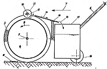
Figure 4: Roller for removing water from a grass pitch (DE 20 25 943 A1).
Nevertheless, many people will rightly mention a match of the 1974 Fifa World Cup that went down in history as the "Wasserschlacht von Frankfurt" (Water battle of Frankfurt) to prove that exceptional climatic conditions like heavy downpours may indeed cause a lot of extra work to keep the pitch playable. Conventional drainage systems of football stadiums (for example, DE 20 2008 006 409 U1) often fail to effectively drain off excess water. In the mentioned World Cup second round match between Poland and Germany that decided who would play in the finals, the pitch was completely under water due to incessant rain, and the groundstaff of Waldstadion in Frankfurt had their hands full getting the pitch in a relatively playable condition with dry rollers like those described in DE 20 25 943 A1 (Figure 4). Probably, this extreme situation could have been avoided with a large-size movable cover based on the principle of an air-supported shelter as suggested in DE 20 2006 004 651 U1.
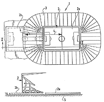
![]() Figure 5: Slide-out mechanism for moving a grass pitch outside the stadium (GB 2 263 644 A).
Figure 5: Slide-out mechanism for moving a grass pitch outside the stadium (GB 2 263 644 A).
In contrast to the above extreme example, today, the grass on the pitch often does not get enough rain, sunlight and air to grow properly due to the design of large football stadiums where towering stands and the roof cast shadows on the pitch. You must take different measures if you want to avoid having to constantly repair bare patches by laying expensive lawn turf, which moreover needs some time before its roots grow into the soil. Counteractive measures include, for example, direct irrigation, for instance by using an underground irrigation system (DE 20 2008 016 954 U1), fertilisation and aeration of the turf of the stadium. Another measure is to remove the entire playing field eg by raising it on hydraulics, like a lift, in relation to the spectators' stands to improve the natural conditions for the grass or by moving the pitch as a whole outside the stadium by means of a slide-out mechanism.
EP 0 916 003 B1 and GB 2 263 644 A (Figure 5), for example, give detailed descriptions of the design of the slide-out mechanism and DE 299 22 797 U1 describes a pontoon-like structure. In all these cases, the pitch is moved out of the stadium to a regeneration area where the grass surface is allowed to grow under almost normal outside conditions.
"Slide-out pitches" were already installed at the Geldredome in Arnhem, Netherlands, and the "Arena auf Schalke" in Gelsenkirchen, Germany. Two examples of lift mechanisms are described in DE 101 35 227 A1 (Figure 6) and DE 101 16 637 C2.
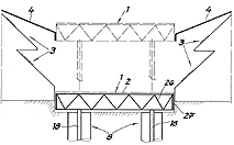
![]() Figure 6: Construction design for lifting the grass pitch relative to the spectators' stands (DE 101 35 227 A1)
Figure 6: Construction design for lifting the grass pitch relative to the spectators' stands (DE 101 35 227 A1)
Instead of making such huge effort to lift or move a pitch, the growth conditions for the natural grass pitch may be improved by clever design features. One option is to install light-reflecting elements into the roof that will increase the light yield due to their slat-like structure (US 6 873 465 B2). However, this will only solve one problem.
For this reason, some of the more complex systems deal with the area directly above the grass pitch. DE 42 08 305 A1, for example, describes a covering facility aiming at creating ideal conditions for the photosynthesis of worn turf by installing artificial light sources and creating a circulated CO2-enriched atmosphere under the protective cover. Similar approaches are described in DE 10 2008 018 459 A1 and in WO 00/57689 A1 (Figure 7):
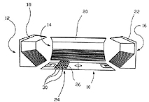
![]() Figure 7: Grass treatment apparatus 26 used on a grass pitch (WO 00 / 57689 A1).
Figure 7: Grass treatment apparatus 26 used on a grass pitch (WO 00 / 57689 A1).
similar to a scanner the apparatus moves over the grass pitch providing favourable conditions for the restoration of the grass. EP 1 269 815 A1 deals exclusively with the application of CO2 gas, if necessary, with additions of water vapour and fertilizer.
DE 10 2004 019 049 B4 recommends stimulating plant growth by combining permanent relatively low-level lighting and LED flashes produced by respective light sources mounted on the undercarriage of a trolley that moves over the lawn surface. The flashes stimulate photosynthesis very effectively due to their high photon flux density. It is also a comparatively energy-efficient regeneration method because there is no need to use bright light sources for permanent illumination.
Such a method to rejuvenate lawn is not a mere figment of the imagination. Since 2002, these technologies have increasingly been used in football stadiums around the world. Clubs and stadium management companies of the English Premier League (FC Sunderland, Newcastle United, Arsenal London) and the Dutch Erendivisie (SC Heerenveen, PSV Eindhoven) are regarded as pioneers in this field. Since the 2009/2010 season, Real Madrid and its Estadio Santiago Bernabéu belongs to this circle of users of the above technology. The lawn there will probably be grateful because Estadio Santiago Bernabéu is one of the darkest stadiums in Europe, a very hostile growing environment for grass. Similar treatment is also applied to the turf grass in the football grounds of Bundesliga in Germany, for example, in the stadiums of Eintracht Frankfurt, VfL Wolfsburg and Bayern München, when no matches are played, so that there is no need for the groundsmen to patch up many bare spots with new turf.
There have been some new developments in turf care in recent years:
The "fibre-reinforced turf support layer" (DE 20 2015 104 216 U1) has reinforcing synthetic fibres which are not biodegradable under normal environmental conditions. When disposing of the turf, the support layer is exposed to temperatures higher than 50° C in an industrial compost plant, which makes the reinforcing fibres biodegradable.
A drainage element (DE 10 2016 103 065 B3) ensures quick drainage after a rain shower. It consists of two textile layers firmly connected with each other by spacer elements, so that the water is drained away more efficiently.
DE 10 2016 000 392 A1 describes a method for promoting growth and regeneration of lawn. A ground treatment device is described by DE 10 2016 103 853 A1: A fluid in the form of gas, compressed air or water can be supplied to the turf via a multitude of injection elements that can be inserted into the soil.
| Publikationsnummer | Jahr | Titel | Kurzbeschreibung |
|---|---|---|---|
| DE 20 2008 016 954 U1 | 2008 | Integriertes Unterflurbewässerungssystem | Unter dem Rasen eingebrachte Bewässerungsanlage, die entsprechend den Witterungsbedingungen die den Wurzeln von unten zugeführte Wassermenge reguliert |
| DE 20 2008 006 409 U1 | 2008 | Rinnenbaustein für eine Entwässerungsrinne | Beispiel für eine gängige Drainagerinne in Fußballstadien |
| DE 10 2008 018 459 A1 | 2008 | Vorrichtung und Verfahren zur Wachstumsbeschleunigung und Regeneration von Rasenflächen | Automatisch verfahrbares, transparentes Zelt, das regenerationsfreundliche Bedingungen für strapazierten Rasen bietet |
| DE 20 2006 004 651 U1 | 2006 | Mobile Abdeckungseinrichtung für Spielfelder | Abdeckplane mit Auszugs- und Koppelmechanismus zum Schutz von Spielfeldern vor unerwünschten Witterungseinflüssen |
| DE 10 2004 019 049 B4 | 2004 | Verfahren zur Stimulation des Pflanzenwachstums | Rasenregenerationsmethode mittels lichtschwacher Dauerbeleuchtung und LED-Lichtblitzen zur Stimulation der Photosynthese |
| US 6 873 465 B2 | 2002 | Installation for increasing the light yield on the playing surface in a stadium | Reflektoren an einem Stadiondach um die Lichtverhältnisse für einen Rasen zu verbessern |
| DE 101 35 227 A1 | 2001 | Arena, insbesondere Sportarena | Liftkonstruktion für ein Rasenspielfeld, um dieses gegenüber den Tribünen anzuheben und dadurch bessere Vegetationsbedingungen zu ermöglichen |
| EP 1 269 815 A1 | 2001 | Vorrichtung zur Begasung von Rasenflächen | Vorrichtung zur Verbesserung der Vegetationsbedingungen für einen Rasen auf einem Fußballplatz |
| DE 101 16 637 C2 | 2001 | Veranstaltungsbau mit vertikal verlagerbarem Gebäudeabschnitt | Liftkonstruktion für ein Rasenspielfeld, um dieses gegenüber den Tribünen anzuheben und dadurch bessere Vegetationsbedingungen zu ermöglichen |
| WO 00/57689 A1 | 2000 | System and method to benefit the growth conditions of grass plants entered in grass courts | Rollenbewegtes Rasenregenerationsgerät für ein Spielfeld |
| DE 299 22 797 U1 | 1999 | Stadion | Spielfeld, das auf Schwimmkörpern gelagert wird und daher leicht verschiebbar ist |
| EP 0 916 003 B1 | 1996 | Sportfeld, insbesondere Fußballfeld, und Verfahren zu dessen Horizontalverlagerung | Schubladenkonstruktion für das Verschieben eines Rasenplatzes vor ein Stadion |
| GB 2 263 644 A | 1992 | Event complex | Schubladenkonstruktion für das Verschieben eines Rasenplatzes vor ein Stadion |
| DE 42 08 305 A1 | 1992 | Verfahren und Vorrichtung zur Wachstumsförderung von Pflanzen | Beleuchtungs- und Begasungsvorrichtung für einen Rasenplatz |
| DE 20 25 943 A1 | 1970 | Vorrichtung zur Aufnahme von Wasser von planierten Flächen | "Wasserwalze" zur Entwässerung von Spielfeldern mit Wasseraufnahmebehälter und Abstreifrolle |
| DE 20 2015 104 216 U1 | 2015 | Faserbewehrte Rasentragschicht | |
| DE 10 2016 103 065 B3 | 2016 | Trockenlegungselement für Pflanzen und dessen Verwendung | |
| DE 10 2016 000 392 A1 | 2016 | Vorrichtung und Verfahren zur Wachstumsbeschleunigung und Regeneration von Rasenflächer | |
| DE 10 2016 103 853 A1 | 2016 | Bodenbehandlungsvorrichtung, Bodenbehandlungssystem sowie Rohrleitung und/oder elektrische Leitung |