The Football Goal
2. The goal frame
Historically, it is difficult to decide which object exactly was the prototype of the football goal. At the early times of modern football, we have not found any granted patents focusing on this subject matter, in contrast to other ball sports (eg. 1885 patent for a polo goal (US 331 756)).
| Publication number | Year | Title | Brief description |
|---|---|---|---|
| US 331 756 | 1885 | Polo Goal | Polo goal as an example from the 19th century using square timber posts and quarter-circular net supports |
2.1 Stabilisation of the frame and anchoring of the goal
The goal must stay in place during the game and at the same time provide excellent stability when stress is applied. However, it is not easy to develop an anchoring system that combines both criteria. Usually the goalposts are inserted into the ground or, in case of free-standing goals with a back ground frame, that frame must be fixed to the ground. Goal anchoring systems are designed to accommodate the different types of goals and may often consist of a combination of the two above mentioned basic varieties.
Since the stability of wood is limited, early inventions were concerned with improving the stability of the goal frame. Besides simple re-enforcing elements for the posts, such as metal strips attached to the rear of the uprights and cross bar (GB 588 334 in 1945), inventions also focused on the rear stabilisation of the goal by additional goal frame elements.
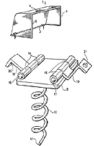
![]() Figure 1: Helically coiled or spiral stake for anchoring a goal assembly (GB 2 268 950 A)
Figure 1: Helically coiled or spiral stake for anchoring a goal assembly (GB 2 268 950 A)
One example is an extended ground bar including a locking device also to be used for transport (DE 298 02 505 U1). Pivoting and locking trapezoidal backstays may add stability. They are linked to the goal frame itself by a sleeve structure (FR 270 52 46 A1). However, the basic principle of this type of "support base structure" has already been known for a long time (eg. DE 28 47 701 A1 with additional braces). Depending on the specific goal design, such support bases may also be anchored to the ground with spiral stakes as further safety measures (GB 2 268 950 A, Figure 1). The fixing means attached to the stake is designed to secure the support base of a goal assembly with a specific geometrical cross-section.
The above direct measures to increase stability are effective on the surface, but for embedding a part of the post in the ground a hole must be drilled for inserting a ground socket and fitted with safety measures to prevent the goal from wobbling or accidental tip-over.
The utility model DE 694 80 51 is a very simple construction: it has a concrete ground socket in which a wooden square-end post may be fastened by means of a wedge-shaped clamp. In addition, a drainage hole is provided at the bottom of the ground socket to protect the wooden post against rot damage from the bottom caused by accumulated rain or melt water.
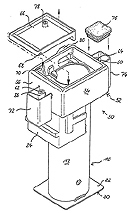
![]() Figure 2: Ground socket for a goal post (DE 202 15 423 U1)
Figure 2: Ground socket for a goal post (DE 202 15 423 U1)
The utility model DE 299 01 330 U1 describes a telescoping structural element for fixing goal posts with adjustment mechanism that allows to accommodate differences in surface levels caused by replacement of turf or levelling measures in the goal area.
Two examples for recent socket developments are DE 202 07 268 U1 (an aluminium post with an integrated protective base that determines how far the post can be inserted into the ground socket) and DE 202 15 423 U1 (guide tube with height-adjustable top to exactly position the goalpost in the socket to bring it to the same level as the pitch surface, Figure 2).
| Publication number | Year | Title | Brief description |
|---|---|---|---|
| DE 202 15 423 U1 | 2002 | Bodenhülse für Pfosten | Levelling device attached to ground socket allows optimum positioning of post to surface level |
| DE 202 07 268 U1 | 2002 | Torpfosten | Goalpost with integrated (welded) protective base for embedded ground socket |
| DE 299 01 330 U1 | 1999 | Befestigungsvorrichtung für Torpfosten | Telescoping fixing device with adjustment mechanism for goal positioning to compensate different surface levels |
| DE 298 02 505 U1 | 1998 | Umsturzsicherung für ein Tor für Ballspiele | Double function of portable goal frame with wheel axles: serving as lockable extension of lower goal frame that prevents accidental backward tip over |
| FR 270 52 46 A1 | 1993 | Cage de buts la practique de sports de ballon, et notamment football, handball | Goal swings in rest position or play position, and is lockable in play position |
| GB 2 268 950 A | 1992 | Sports equipment anchoring device | Spiral stake that can be screwed into the ground for anchoring goal assemblies |
| DE 28 47 701 A1 | 1978 | Tor für Ballspiele | Goal with support base structure for added stability |
| DE-GM 694 80 51 | 1969 | In den Erdboden einsetzbarer Ständer | Concrete socket for square post with wedge-shaped clamps and drainage holes |
| GB 588 334 A | 1945 | Improvements in the Construction of Football and like Goals | Metal re-enforcing strips attached to the rear of the uprights and crossbar; cross section of the ground sockets changes from rectangular to elliptical shape |
2.2 Structure and geometry of uprights and crossbar
The geometric shape of uprights and crossbar and its influence on the motion of the ball has been a question widely debated ? even before the Wembley goal of 1966.
Formerly, rectangular cross sections were standard in most of the stadiums while quasi-circular or elliptical shapes are almost exclusively used today. One reason for that is the nearly unpredictable bounce of the ball if it hits the edge of the rectangular posts or crossbar and the other reason is the clearly increased risk of injury of players.
That is why inventors early came up with the idea for uprights and crossbars with circular cross-sections. In 1922, GB 183 677 A by John Claude Perkins of Nottingham was the first patent document on this topic. In this document mostly elliptical cross sections are preferred for the goal face. The crossbar is additionally strengthened by a steel rod in a channel in the body of the crossbar which acts as a truss for better stability and prevents the crossbar from sagging down in the middle.
Another solution is to mount round goal posts and crossbars in front of the respective rectangular post or bar where they are rotatably supported (DE-PS 832266) patent of 1950. Forces acting on the goal frame would be deflected by this mechanism, making the bounce of the ball more predictable and reducing the risk of injury.
![]() Figure 3: Rotatably supported cylindrical elements for goal posts and cross bar (DE 894372).
Figure 3: Rotatably supported cylindrical elements for goal posts and cross bar (DE 894372).
The patent document DE 894372 describes a further development of this idea. The posts fitted in front of the goal frame consist of cylindrical or spherical elements arranged one after the other like beads on a string (see Figure 3).
This principle is extended in the patent DE 1011791 by using elements that have cross sections shaped like gear wheels or sprocket wheels.
The final step of that development probably is a goal whose posts and crossbar consist of a rotatable casing of roller segments which do not have to be specifically fitted in front of the goal frame but themselves form the goal frame (DE-OS 2 122 323).
However, the goal post designed as a "double post" with two pipes fitted one behind the other did not become popular (DE-AS 1035546).
| Publication number | Year | Title | Brief description |
|---|---|---|---|
| DE-OS 2 122 323 | 1971 | Tor, insbesondere Fußballtor | Goal with uprights and crossbar constructed of a rotatable casing of roller segments which form the goal |
| DE-AS 1 035 546 | 1958 | Torbegrenzung für Ballspiele | Double post construction made of two pipes arranged one behind the other |
| DE-PS 1 011 791 | 1954 | Torbegrenzung für Ballspiele | Goal with rotatable post segments having cross sections shaped eg. like gear wheels or sprocket wheels |
| DE-PS 894 372 | 1951 | Torbegrenzung für Ballspiele | Goal with rotatable post segments and a likewise rotatable crossbar fitted in front of a goal made of rectangular posts/ crossbar |
| DE-PS 832 266 | 1950 | Tor für Rasenspiele | Goal with rotatable posts mounted on shafts and a rotatable crossbar fitted in front of a goal made of rectangular posts/ crossbar |
| GB 183 677 A | 1922 | Improvements in the Construction of Foot-ball and like Goals | Goal face with elliptical cross section and crossbar reinforced by steel rod |
2.3 Safety and security measures
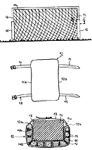
![]() Figure 4: Padded post (DE-GM 7106711).
Figure 4: Padded post (DE-GM 7106711).
It doesn't matter whether you collide with a round aluminium post or a square wooden post ? it hurts all the same. A safety measure capable of absorbing an impact (like that proposed in the utility model DE-GM 7106711), will not become established in practice, since it would interfere with the play of the ball during the game (see Figure 4). However, some inventors have not been put off by this fact and file patent applications focusing on this aspect (eg US 7 150 690 B1)
The utility model DE-GM 8131492 provides a solution to prevent unauthorised use of goals. The goal can be locked by means of a pulldown bar fastened to the post.
| Publication number | Year | Title | Brief description |
|---|---|---|---|
| US 7150 690 B1 | 2006 | Soccer goal padding | Foam-padded goal post |
| DE-GM 81 31 492 | 1981 | Tor für Ballspiele, insbesondere Fußballtor | Goal with pulldown lockable bar to prevent unauthorised use of the football goal |
| DE-GM 71 06 711 | 1971 | Vorrichtung als Kantenschutz an Pfosten von Fußball-Handball oder Hockey-Toren | Protective padding with strap latch for goals with rectangular posts |
2.4 Moving goals
When large-scale work on the pitch is pending or goal maintenance is due, the goals are completely removed from their places. Formerly, they had to be completely disassembled for this purpose. Today this is no longer common. However, despite of the weight-saving construction, moving a goal is not easy owing to its dimensions and some technical aids are necessary.
One example is a lifting and lowering device for football goals (utility model DE 7146974). It consists of a height-adjustable T-beam mounted on a two-wheel trolley shaped like a gun carriage. A hydraulic or cable mechanism for the T-beam with a recess fitting the crossbar can lift the entire goal off its moorings. The T-beam can be swivelled by 90 degrees on the carriage for space-saving transport of the goal.
![]() Figure 5: Carrier clamp for goals (DE-OS 29 40 100).
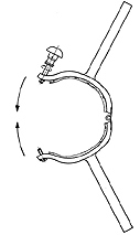
Figure 5: Carrier clamp for goals (DE-OS 29 40 100).
Muscle power alone has to be used for applying this carrier clamp, described in DE-OS 2940100. The clamp possesses two handles and a hinge for opening/ closing the clamp. The clamp closely encircles the post and is fastened and locked with a set screw (see Figure 5). When applied to both posts, the clamps enable two persons to lift the goal off its moorings and carry it away.
The wheel kit, shown in DE 20303822 (utility model) consists of a U-shaped sheet metal support element and of a two-wheel axle with a locking device. Before using the wheel kit, the goal post must be prepared by installing specific retention pins to allow safe roll-away transport.
In contrast to the above wheel kit, the wheels described in DE 29802505 (utility model) are permanently fixed to the goal frame and unfold toward the rear.
Naturally, different criteria and aspects apply to the use of transport aids for indoor football goals. Please refer to DE 3811506 A1 as an example.
| Publication number | Year | Title | Brief description |
|---|---|---|---|
| DE 203 03 822 U1 | 2003 | Rädergarnitur für Ballspieltore | Two-wheel transport kit for goals, whose posts must be prepared for transport by means of retention pins |
| DE 298 02 505 U1 | 1998 | Umsturzsicherung für ein Tor für Ballspiele | Double function of portable goal frame with wheel axles: serving as lockable extension of lower goal frame that prevent accidental backward tip over |
| DE 38 11 506 A1 | 1988 | Vorrichtung zur Überführung eines Gegenstandes z.B. eines Tores zwischen zwei Positionen | Mechanism for putting up and storing a football goal against the wall of a gymnasium |
| DE 29 40 100 A1 | 1979 | Fußballtor-Auszieher | Carrier clamp with two handles and a hinge to tightly fasten around the post |
| DE 714 69 74 U1 | 1971 | Fußballtor Hebe- und Senkgerät | T-beam mounted on a trolley shaped like a gun carriage for transporting non-collapsible football goals |
2.5 Collapsible goals
The requirements of multipurpose fields, not exclusively used for playing football, led to the development of goals that can quickly be assembled and disassembled. Today, collapsible goals are mostly intended for practice or youth football. However, the issue itself is still posing a great challenge for the creativity of inventors who continue to actively work on the issue.
The most frequent ideas concern the folding techniques on the basis of hinges or push-fit connections to save as much space as possible.
![]() Figure 6: Collapsible goal (DE 37 22 200 A1).
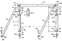
Figure 6: Collapsible goal (DE 37 22 200 A1).
Goals designed according to GB 945760 A are hardly utilisable in a game since the frame of rods and/or tubes with different diameters do not provide a flush surface. DE 37 22 200 A1 does no longer show that deficiency. It describes a seemingly crude frame of square wooden posts with tenons, spikes and fastening joints, which can be easily assembled (Figure 6).
The same applies to the goal of round posts with elbow brackets described in DE-OS 20 34 663, which was filed 17 years earlier. An elbow bracket serves as net support and as securing contrivance for two post components.
DE 3434034 A1 shows a collapsible goal to be assembled from pipes and changes size to meet the respective needs. By simply tipping over the goal and changing its height, the goal face can be adjusted to the mode of play, depending, for example, on the number and age of the players.
EP 0934761 A1 and DE 20 2004 012 299 (utility model) are examples for the folding and hinge mechanisms for the space-saving disassembly of a goal. The latter invention concerns a combination of swivel backstays and a collapsible net support ground bar.
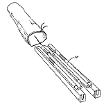
![]() Figure 7: Carrier bag and collapsible goal (EP 0 938 354 B1).
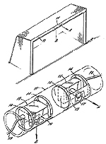
Figure 7: Carrier bag and collapsible goal (EP 0 938 354 B1).
Meanwhile miniaturisation of collapsible goals has advanced to the point that they can be folded and transported in reasonably manageable containers in a space-saving manner (EP 0938354 B1 (Figure 7), GB 2334896A).
The demand for the smallest packing size can actually only be met by inflatable goals. The appearance of such a goal, as shown in DE 20 2004 001 489 (utility model), hardly has anything in common with a regular football goal suitable for tournaments.
| Publication number | Year | Title | Brief description |
|---|---|---|---|
| DE 20 2004 012 299 U1 | 2004 | Zusammenklappbares Fußballtor | Goal with swivel backstays and collapsible lower net support bar |
| DE 20 2004 001 489 U1 | 2004 | Aufblasbarer Torrahmen | Goal frame with attached net consisting of inflatable air reservoirs |
| GB 2 334 896 A | 1998 | Portable Goal and net | Folding goal whose container serves as goal post |
| EP 0 938 354 B1 | 1997 | Folding soccer goal | Folding goal with appropriate carry bag |
| EP 0 934 761 A1 | 1997 | Cage de but mobile notamment pour jeux de ballon | Folding goal |
| DE 37 22 200 A1 | 1987 | Fußballtor | Collapsible goal made of square wooden posts with mortise and tenon and fastening joints for the back support of the goal frame by means of ground-anchored bars |
| DE 34 34 034 A1 | 1983 | Bewegliches Tor für Sportfelder | Collapsible goal made of pipes; the goal size can be changed easily by tipping it over |
| DE-OS 20 34 663 | 1970 | Fuß- oder Handballtor | Collapsible goal made of round posts with net support elbow bracket used as securing contrivance for two post components |
| GB 945 760 A | 1961 | Collapsible Goal Frame | see title |
2.6. Special goal developments
Goal boards for practising football target shooting and toy goals used mainly by children are presented in the chapter "Miscellaneous".
The special goals in this chapter are not exotic but were developed for use in regular football games.
Goals are for examples equipped with sensors providing measurements to referees to assist them in taking decisions.
As early as in 1970, DE-OS 205 1386 proposed the use of a specifically equipped ball as resonant or pulser reacting to sensors in the goal frame. This technology would automatically register a goal.
![]() Figure 8: Crossbar with integrated camera (EP 0 345 982 A1).
Figure 8: Crossbar with integrated camera (EP 0 345 982 A1).
Cameras mounted in the goal frame have the same purpose, but at the same time they can also take pictures of the game from an unusual angle for TV coverage. In EP 0 345 982 A1 two cameras are sufficient: one camera pointing straight down at the goal-line and the other camera pointing in the direction of the other goal (Figure 8). In GB 2 342 050 A a plurality of video cameras are mounted in many different positions of the uprights and crossbar.
The inventors also thought about the "visibility" of goals. The utility model DE 203 06 580 describes a goal that will flash when the referee hits a button or even automatically register a goal when a goal is scored. For this purpose, lights are installed in the goal frame, which do not interfere with the mechanical properties of the goal frame.
| Publication number | Year | Title | Brief description |
|---|---|---|---|
| DE 203 06 580 U1 | 2003 | Tore oder Torrahmen für Sportarten, vorzugsweise Fußball mit Beleuchtung | Goal frame eg. with integrated lights flashing when goal is scored |
| GB 2 342 050 A | 2000 | Goal posts | Goal monitoring system with a plurality of cameras mounted on the goal posts and crossbar |
| EP 0 345 982 A1 | 1988 | Means for mounting a camera for sports coverage | Camera mounted in the crossbar |
| DE-OS 205 13 86 | 1970 | Verfahren zum automatischen Erkennen von Treffern bei sportlichen Spielen | A specifically equipped ball will generate signals in sensors installed in the goal frame enabling display of score |