The Football (Soccer Ball)
6. Smart footballs
People often perceive training and game situations differently. For this reason efforts are being made to offer referees or coaches additional tools for better assessing the player's action (eg. his shooting force) and the ball behaviour (eg. its position on the pitch). These developments can be summarised under the heading "smart football".
FIFA refused to use technical tools for a long time. In 2012, however, they finally allowed the goal-line camera and a chip in the football. At the 2014 FIFA World Cup in Brazil, the smart technology was used for the first time. It has also been standard in the Bundesliga since 2015.
Video evidence will also be used for the first time at the 2018 World Cup. But that took quite a long time: Many exciting inventions were hardly even noticed by the FIFA for a long time, while some of them found recognition only late and very few of them were finally admitted.
Here we present the history of these developments and the different concepts. You can also find more on this topic under "Goal line technology and video proof".
6.1 A chip in the football
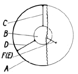
![]() Figure 14: Tetrahedral suspension of an object in the interior of a football (DE-PS 829 109)
Figure 14: Tetrahedral suspension of an object in the interior of a football (DE-PS 829 109)
Any additional component which is incorporated in the ball - such as a sensor - is an interfering element that must be compensated. Due to the ongoing miniaturisation of electronic components and innovative powering techniques it is now possible to equip a ball with sensors without adding any significant weight. For balancing reasons, these components are preferably lodged in the ball centre.
There are mainly two solutions for lodging electronic components in the ball centre:
- an elastic but locally stable suspension with at least two fixed points in the ball interior;
- the full central housing of components within a protective material (eg. foam, bladder composed of several chambers).
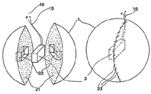
![]() Figure 15: Foam rubber protected ball sensor (FR 2 667 510 A1).
Figure 15: Foam rubber protected ball sensor (FR 2 667 510 A1).
DE-PS 829 109 from 1952 presents an early concept for suspending an object in the ball centre. It provides for a system of elastic fastening straps in a tetrahedral shape (Figure 14).
DE 200 04 174 U1 is the first document to explicitly propose to use an elastic suspension in tetrahedral form for fixing a position transmitter, lodged within the ball, for determining the position of the ball on the pitch.
FR 2 667 510 A1 (Figure 15) is an example for the inclusion of an object in a protective material. The football bladder consists mainly of full foam rubber and has a clearance in the ball centre for housing a transmitter. The transmitter is fixed in a largely stable position even during the game and is well protected against the forces occurring when the ball is shot.
The lodging of an electronic component in central recesses of a football bladder provided with suitable chambers falls within the same category. Examples are contained in documents DE 103 50 300 A1, DE 103 61 826 A1 and DE 10 2004 045 176 A1 (Figure 16).
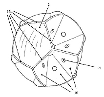
![]() Figure 16: Bladder divided into chambers by reinforcing surfaces and equipped with a transmitter located at the centre (DE 10 2004 045 176 A1).
Figure 16: Bladder divided into chambers by reinforcing surfaces and equipped with a transmitter located at the centre (DE 10 2004 045 176 A1).
The football claimed in DE 10 2004 045 176 A1 has ao. a bladder whose interior is crossed by planar reinforcing surfaces and an electronic transmitter lodged at the ball centre by means of these reinforcing surfaces (Figure 16). This design absorbs the mechanical loads and reduces deformation occurring during the game, but also accelerations of the transmitter within the ball. Since the transmitter, due to this particular arrangement, is prevented from oscillating freely eg. if the ball is hit simultaneously by two players, it is possible to exactly locate the ball centre even in difficult game situations. This is important to determine eg. whether the larger part of the ball has passed the goal line. The application also proposes to equip the multi-chamber bladder with several elastic pulling elements, arranged in form of a tetrahedron (compare Figure 14), that maintain the transmitter in a predetermined position within a separate chamber at the bladder centre.
| Publication number | Year | Title | Brief description |
|---|---|---|---|
| DE 10 2004 045 176 A1 | 2004 | Blase | Football with chambered bladder and tetrahedral suspension of a sensor suitable for localisation |
| DE 103 61 826 A1 | 2003 | Sportball, insbesondere Fussball | Football with two interconnected bladders for maintaining an electronic component in a central position within the ball |
| DE 103 50 300 A1 | 2003 | In Kompartimente unterteilter Ball mit integrierten elektronischen Übertragungsmitteln | Football with chambered bladder and centrally lodged sensor suitable for localisation |
| DE 200 04 174 U1 | 2000 | Spielgerät, Einrichtung zur Erfassung des Spielgeräts sowie Teile dieser Einrichtung | Elastic tetrahedral suspension of a position transmitter in the ball centre |
| FR 2 667 510 A1 | 1990 | Dispositif destiné à la practique d'un nouveau jeu sportif individuel ou d'équipe | Transmitter located in the centre of a ball, protected by foam rubber housing |
| DE-PS 829 109 | 1950 | Luftgefüllter, dünnwandiger Spielball | Tetrahedral suspension of a weight element in the centre of a football by means of straps |
6.2 General remarks on "flying sensors"
When a solution has been found for lodging a sensor in the centre of the ball that will work under game conditions, an appropriate sensor chip must be chosen, depending on the kind of information required. In the developments presented, chips are mostly part of a larger measuring field where the sensor communicates with other components of this field via radio signals. It is not necessary to remove the sensor chip in order to read out data. Anybody will easily understand that this is a basic requirement for the utilisation in practice, eg. in regular matches or training units.
This should be mentioned, above all, since more than fifteen years ago there were in fact sensors, lodged in footballs, that had to be removed after measuring like tachographs.
Against this background, fully mechanical devices for determining the ball speed, such as described in DE 195 49 231 A1, are rather uncommon. This document presents a mechanical timer integrated in the ball for measuring the time between shooting and impact. Two housing components rotate relative to each other in the manner of a countdown timer. The displacement is measured. If the distance between shooting point and impact point is known, it is possible to calculate the velocity of the ball. The velocity allows to determine the shooting force.
| Publication number | Year | Title | Brief description |
|---|---|---|---|
| DE 195 49 231 A1 | 1995 | Ball mit eingebauter Vorrichtung zur Messung und Anzeige der Ball-Fluggeschwindigkeit | Mechanical method for determining the shooting force by measuring the velocity of the ball |
6.3 Determining the position on the pitch
An - active or passive - chip in a football alone does not yet allow to determine the true position of the ball on the pitch. Rather, sophisticated methods are required for localising the chip. The actual solution depends on whether the position of the chip - and thus the ball - is to be determined by means of inductive or optical systems, or using
radio waves.
As a rule, the chip embedded in the ball must exchange data with a complex measuring system installed on the sidelines and/or the pitch.
6.3.1 ... by means of magnetic fields or electromagnetic waves
A football is often equipped with a radio signal transmitter or transponder permanently emitting signals in the millisecond range. These signals allow to locate the ball within a net of coordinates established between several stationary receivers (see DE 10 2007 046 366 A1, DE 102 52 934 A1 - Figure 17). The net of coordinates should extend over the whole pitch and even beyond. Since the area to be monitored is comparatively large and since the measuring accuracy must be in the centimetre range, at the least, a complex signalling processing system is required that works nearly in real time.
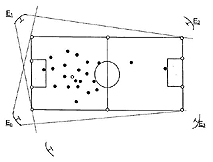
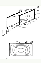
![]() Figure 17: System for determining the position of a football and players by means electromagnetic waves (DE 102 52 934 A1).
Figure 17: System for determining the position of a football and players by means electromagnetic waves (DE 102 52 934 A1).
DE 103 50 300 A1 and DE 10 2004 045 176 A1, already mentioned under item 6.1, relate to footballs whose positions can be determined fairly precisely. It is of course also possible to limit monitoring to the goal area or the sidelines, as proposed in US 2006/0 247 076 A1 or WO 2006/094 508 A1.
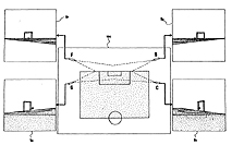
DE 10 2007 046 366 A1 and EP 1 852 155 A1 (Figure 18) offer another approach. In the latter case, coils located on the pitch in the goal area (300) and/or other suitable spots in proximity to the pitch generate interacting static magnetic fields that vary according to the laws of physics depending on the distance from their source. The "magnetic field pattern" (600) thus generated contains spatial information that can be used for establishing a magnetic coordinate system. Since the pattern of the magnetic field over the entire pitch or the goal area, in particular, is known, it is possible to accurately determine the position of the ball provided that it is equipped with a magnetic field sensor that registers that field and transmits the measurement values to an analysing system.
![]() Figure 18: Magnetic localisation system for sports balls (EP 1 852 155 A1)
Figure 18: Magnetic localisation system for sports balls (EP 1 852 155 A1)
Further inventions suggesting localisation by means of magnetic fields at the goal itself or in the goal area were filed for patenting until shortly before the mentioned FIFA decision. A few examples are DE 10 2007 048 818 A1, DE 10 2007 009 232 B3, and - specifically - DE 10 2007 052 946 A1. In the last-mentioned case, localisation is provided by means of magnetic alternating fields generated between a conductor-equipped crossbar and likewise equipped goal line, via a magnetic field sensor contained in the football.
One of the latest developments is a ball with an elastically deformable coil structure (EP000002877252B1).
| Publication number | Year | Title | Brief description |
|---|---|---|---|
| DE 10 2007 052 946 A1 | 2007 | Vorrichtung, Verfahren, Computerprogramm und System zum Erkennen, wenn ein Objekt oder eine Person eine durch ein magnetisches Feld markierte Grenze überschreitet | Determining the position of a football equipped with a magnetic field sensor via its position in relation to a magnetic alternating field between the goal line and the crossbar |
| DE 10 2007 048 818 A1 | 2007 | Automatische Positionsbestimmung eines Objektes, insbesondere eines Fußballs | Determining the position of a football equipped with a magnetic field sensor via its position in relation to a magnetic alternating field between electric conductors in the goal area |
| DE 10 2007 046 366 A1 | 2007 | Konzept zur Positionsmessung durch Phasenvergleich eines modulierten Signals | Electromagnetic localisation method with a multitude of receiving aerials registering radio signals emitted by the ball and the players |
| DE 10 2007 015 493 A1 | 2007 | Bewegungsbereich für einen mobilen Gegenstand und Auswertungsvorrichtung zum Feststellen einer Position eines mobilen Gegenstands | Determining the position of a football equipped with a magnetic field sensor by means of static magnetic fields and their three-dimensional geometry |
| DE 10 2007 009 232 B3 | 2007 | Vorrichtung und Verfahren zum Erzeugen eines Magnetfeldes in einem Torraum zur Torentscheidung | Determining the position of a ball by means of inductive effects within a coil system |
| EP 1 852 155 A1 | 2006 | System und Verfahren zur Positionsbestimmung eines beweglichen Objekts mittels Magnetfeldern | Determining the position of a football by means of static magnetic fields and their three-dimensional geometry |
| WO 2006/094 508 A1 | 2005 | Goal detector for detection of an object passing a goal plane | System for goal monitoring by means of electromagnetic waves |
| DE 10 2004 045 176 A1 | 2004 | Blase | Football with chambered bladder and tetrahedral suspension of a sensor suitable for localisation |
| DE 103 50 300 A1 | 2003 | In Kompartimente unterteilter Ball mit integrierten elektronischen Übertragungsmitteln | Football with chambered bladder and centrally lodged sensor suitable for localisation |
| US 2006/0 247 076 A1 | 2003 | Goal detector for detection of an object passing a goal plane | System for goal monitoring by means of electromagnetic waves |
| DE 102 52 934 A1 | 2002 | Verfahren zur kontinuierlichen Echtzeitverfolgung der Position von wenigstens einem mobilen Objekt sowie zugehörigen Sendern und Empfängern | Method for locating the position of the football and the players on the pitch by means of microwaves |
6.3.2 ... by means of optical systems
![]() Figure 19: Optical localisation system for footballs (EP 1 402 476 B1)
Figure 19: Optical localisation system for footballs (EP 1 402 476 B1)
In addition to the mentioned methods it is, on principle, possible to localise a ball by optical means. The football may - but need not - be equipped with electronic components. The relevant systems function eg. using high resolution camera systems covering the whole pitch (EP 1 402 476 B1 - Figure 19) or photo detectors (eg. light beams) at or within the game markings (eg. WO 2007/125 476 A1 with additional transponder embedded in the ball).
As shown in DE 10 2007 049 147 A1 (Figure 20), a camera system 26,28 can also be combined with other optical sensors such as PMDs 22 or LiDAR, promising a specifically high density of information and thus high precision.
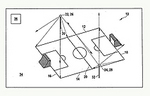
![]() Figure 20: Combined optical localisation system for sports balls (DE 10 2007 049 147 A1).
Figure 20: Combined optical localisation system for sports balls (DE 10 2007 049 147 A1).
In addition, partial solutions by optical means are also known, for example from WO 2006/111 928 A2, specialising on optical real time determination of offside situations. To complete the picture, the optical system according to GB 2 357 207 A should be mentioned as well. It is frequently used in cricket or tennis matches and hoped to make a career in football too.
| Publication number | Year | Title | Brief description |
|---|---|---|---|
| DE 10 2007 049 147 A1 | 2007 | Sensorsystem zum Erfassen von Bewegungsabläufen oder Spielsituationen beim Sport | Combined optical positioning system using cameras, PMDs and/or LiDAR |
| WO 2007/125 476 A1 | 2006 | Marking system for sport areas | Positioning system with photo detectors and a transponder in the ball |
| WO 2006/111 928 A2 | 2005 | Method and system for the detection and the classification of events during motion actions | Optical system for detecting offside situations |
| EP 1 402 476 B1 | 2002 | System and method for the measurement of the relative position of an object with respect to a point of reference | Optical method for determining the position of an object by means of several cameras |
| GB 2 357 207 A | 1999 | Ball tracking and trajectory prediction | Ball tracking system known from cricket and tennis |
6.4 Multi-sensor systems around the football
It is not uncommon to equip a football with a chip that is able to measure a variety of physical parameters.
DE 103 38 620 A1, for example, describes a method for determining the position of the ball on the pitch and the forces acting upon the ball simultaneously. The football is equipped with a radio wave transmitter which is in active communication with stationary receiver units, set up outside the pitch for determining a position within the coordinate system thus created. In addition, the ball is fitted with pressure and acceleration sensors. The sensors transmit the collected data via the transmitter.
Referees need to know the position of the ball in relation to the player, eg. for making offside decisions. To assist the referee, DE 100 29 459 A1 proposes to equip both the ball and the players with chips, which are attached to the players' clothes. Other documents from this technical sphere concern eg. the calibration of sensors (DE 100 29 456 A1), peripheral conditions (DE 100 55 289 A1) and the processing of collected data (DE 100 29 463 A1, DE 100 29 464 A1).
Other examples where some of the aspects discussed here are considered from the referee's view, can be found in the chapter "Referee equipment".
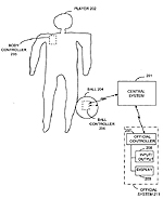
![]() Figure 21: System for measuring several physical parameters on the ball and for identifying players (US 2006 / 0 178 235 A1).
Figure 21: System for measuring several physical parameters on the ball and for identifying players (US 2006 / 0 178 235 A1).
Since people today just love statistics, it seems important to collect personal data in order to have figures about a player's performance, eg. his ball handling, tackling and efficiency of actions. To collect data, it is not only necessary to identify and localise the ball but also each individual player by electronic means. In order to record eg. the kind and number of ball contacts it is necessary for the player to carry an individual RFID tag, just like a milk carton in a modern supermarket. The RFID tag is activated when the ball, which carries a similar transponder, gets near enough to one or several players to identify them. If the ball is touched in the course of the game, this ball contact will be registered and the type of ball handling will be recorded by a series of sensors embedded in the ball before the data are finally transmitted to a central system. This central system analyses the contact information to assess the player's performance, assist referees in their decisions or to produce all types of statistical data, as described eg. in US 2006 / 0178 235 A1 (Figure 21), DE 10 2007 001 820 B3 or DE 10 2005 036 355 A1.
We cannot yet tell whether sensor equipped footballs will eventually be adopted for use in regular matches. This will depend on the football associations' further decisions.
| Publication number | Year | Title | Brief description |
|---|---|---|---|
| DE 10 2007 001 820 B3 | 2007 | Konzept zur Erkennung eines Kontakts mit einem Spielgerät | Magnetic field sensor within the football registers any ball contacts via a magnetic field created at the player by a field generator |
| US 2006/0 178 235 A1 | 2006 | Apparatus and method for determining participant contact with a sports object | System for determining the frequency and kind of contacts of one or more players with a sports ball |
| DE 10 2005 036 355 A1 | 2005 | Verfahren zur Erfassung der Kraft- und Bewegungsverhältnisse an einem Spielgerät | Sensor for determining the forces acting upon a sports ball and system for monitoring players |
| DE 103 38 620 A1 | 2003 | Ballsensor | Football equipped with radio wave transmitter for determining the position, and other sensors |
| DE 100 55 289 A1 | 2000 | System zur Bestimmung der Position eines Objektes | Peripheral components for determining the position of a football on the pitch |
| DE 100 29 464 A1 | 2000 | Einrichtung und Verfahren zur medialen Aufbereitung von statischen Zuständen und/oder Bewegungsabläufen | Method for processing data that allow to determine the position of a football |
| DE 100 29 463 A1 | 2000 | Auswerteeinheit und Verfahren zur Auswertung von statischen Zuständen und/oder Bewegungsabläufen | Method for processing data that allow to determine the position of a football |
| DE 100 29 459 A1 | 2000 | Einrichtung zur Erfassung der Position und/oder Bewegung eines Objekts und/oder Lebewesens sowie Teile dieser Einrichtung | Device for determining the position of the ball in relation to the player's position; ball and player are fitted with transmitters |
| DE 100 29 456 A1 | 2000 | Verfahren zur Eichung eines Sensorsystems | Device for determining the position of the ball in relation to the player's position; ball and player are fitted with transmitters |
| DE 100 29 459 A1 | 2000 | Spielgerät, Einrichtung zur Erfassung des Spielgeräts sowie Teile dieser Einrichtung | Elastic tetrahedral suspension of a position transmitter in the ball centre |